Our standard is to project the same level of detail down from the plan. Whenever Im drawing something thats nearly but not quite horizontal or vertical Revit forces it to be aligned to x-y axes.

Solved Iso Surface Roughness Symbol Missing Roughness Autodesk Community Fusion 360
Add dimensions ordinate dimensions hole callouts datums geometric tolerances weld and surface finish symbols notes tables images and balloon callouts.

. F-weld F F-welding can be used to weld two separate parts of metal straight up or at a slight angle. Groove Welds G-Groove Welds G can be made in the groove if they can penetrate through the lower surfaceThis type of weld. It uses a symbolic language on engineering drawings and computer-generated three-dimensional solid models that explicitly describe nominal geometry and its allowable variation.
There is no additional fee to use Bluebeam Drawings but you are required to have at least Revu 2018 or later and your annual maintenance must be current and active. Or you can download the Drawings App for an even smoother experience. Im doing as-builts of a historic structure and the walls are very slightly out of alignment with the x-y axes.
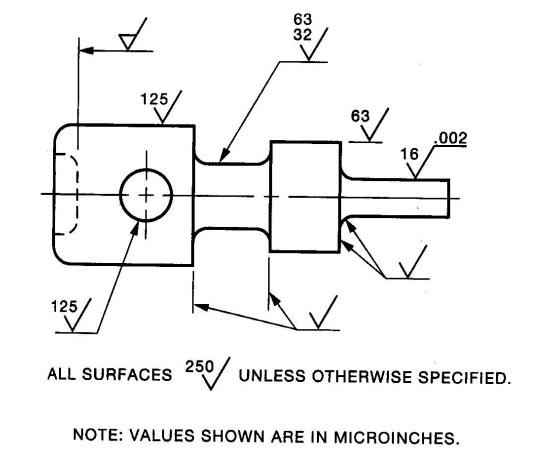
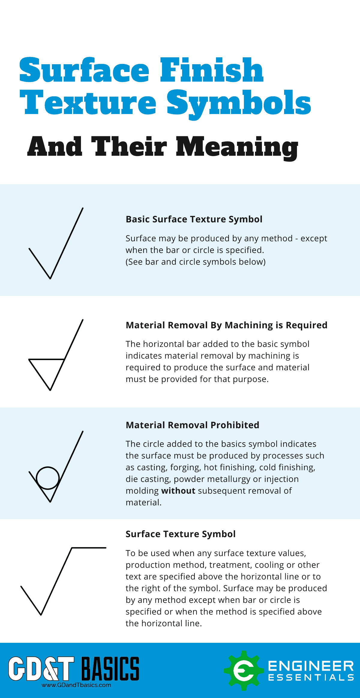
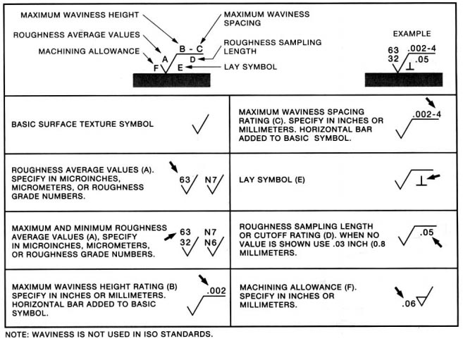
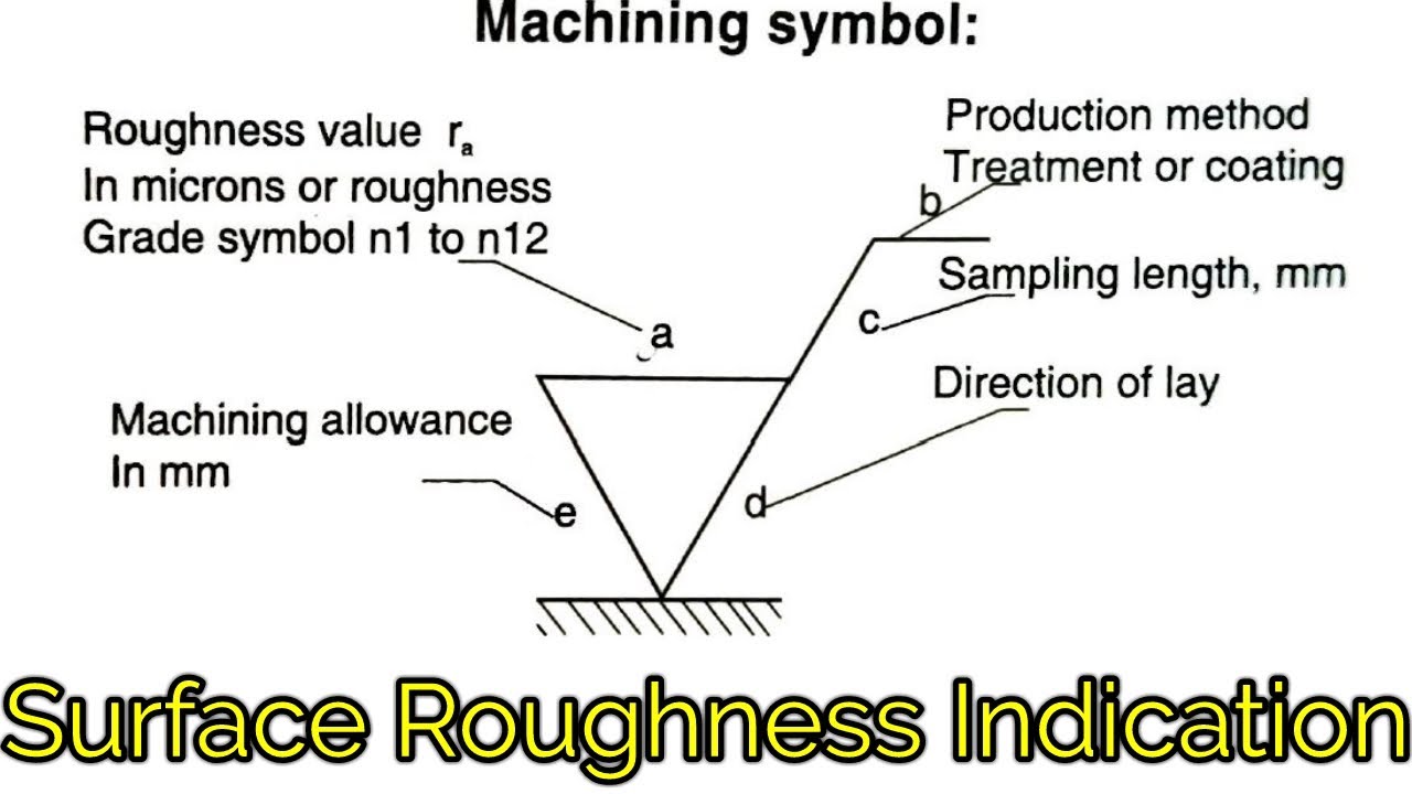
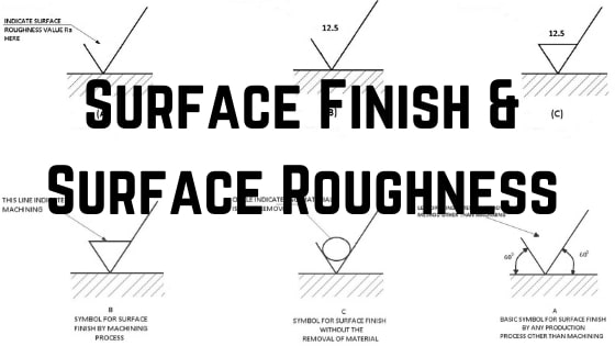
An italic f Latin small letter f written on a line representing a surface was an old way of indicating that the surface was to be machined rather than left in the as-cast or as-forged state. There are many variations of the surface texture symbol but most often it is used with a microinch or micrometer value callout that specifies the roughness of a surface. The f came from finish in the sense of machine finish as opposed to raw stockcastingforging.
This view is important to depict cabinet configuration and finish callouts. Elevation View Drawings are generally shown as if you were standing directly in front of the item. Relation to Other GDT Symbols.
It tells the manufacturing staff and machines what. Geometric Dimensioning and Tolerancing GDT is a system for defining and communicating engineering tolerances and relationships. If a simple surface is called out such as a radius on a corner a height gauge can be used to trace the part as long as the gauge can stay the same distance away from the surface as rotates around the surface.
Drawing callouts marked KEY define. A symbol for defining the surface finish of a part. This shows up in the right spot when lookin at the building and surrounding area in 3D and when looking in plan view at say the roof apex height around 12m from ground level but on other certain levels like the second floor level the topo disappears.
When I placed the toposurface I was careful to place it at 150mm below the finished floor level of the warehouse. Simply open the app click on a project and view the latest mobile-optimized plans for free. The difference between them is that.
Onshapes CAD drawings can be annotated to comply with ANSI and ISO drawing standards. Profile of a surface is the 3D version of profile of a line. Develops the only product design platform that combines 3D CAD PDM collaboration and analytics tools in the cloud.
I dont want that but dont know how to turn it off so that.
Complete Surface Finish Chart Symbols Roughness Conversion Tables
The Basics Of Surface Finish Gd T Basics
Complete Surface Finish Chart Symbols Roughness Conversion Tables

Roymech Surface Finish Texture Symbols
Surface Roughness Indication Symbols Surface Roughness Symbol Indication In Hindi Youtube
Surface Finish Surface Roughness It S Indications Symbols

Surface Surface Finish Symbols Surface Roughness Symbol

Surface Roughness Symbol In Drawings Mechanical Engineering General Discussion Eng Tips
0 comments
Post a Comment